
Cmelak
The decision to make this model had an interesting beginning in that John was looking for a model that he could fit a Valach 250 radial engine in and that would be a practical everyday model to fly at his local flying field. These criteria required a model that was simple and quick to put together and would be happy flying in and out of a small area. The Cmelak design met this requirement and the original idea was to design and build one from scratch in normal Ghost Squadron style. Whilst researching the design it was discovered that Airworld made a model in the size being considered, and so it was decided to purchase a kit and build that.
The build has been documented in a series of articles in R/C Scale International Jan/Feb 2022 and March/April 2022 editions. The text of the articals are included below.
Cmelak
It is funny what draws modellers to build a certain model, it could be the look, the flying style or even a particular colour scheme but this story starts with the motor. Actually not the motor I used but a Fiala Motors Valach 420 radial. I have the 420 5 cylinder radial in my ½ scale Klemm 25 and the sound and ease of operation of the motor makes flying the Klemm a real joy. When the Fiala produced the 250 radial I immediately wanted one as whilst the Klemm is a great model it is too big for that quick nip down the flying field for an hour or so days. I felt the 250 could be put in a more easily manageable airframe that was easy to transport and quick to rig at the field….but what airframe to pick.
Whenever I start a new project I have a clear idea of what I want to achieve with the model and this will drive the final decision. In this case, it needed to be a simple practical model that I could fly at my local field, be easy to store, transport and quick to rig. These criteria lead me to look for a robust model with a fixed undercarriage and without struts or other fittings that would add time to the rigging once at the field.
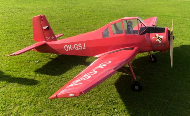
Several different models were considered before I saw a picture of the Cmelak. This looked like a good candidate, a bit unusual in design, which I like, but with a robust undercarriage and easy to assemble with plug on wings and a simple bolt on tail. I knew Airworld made a kit of the model so a good look at their website convinced me that this was the model to pick. More research showed that most Cmelak’s were finished in yellow but having just finished a Bucker Jungmeister in yellow I wanted something different and I found a pink one with interesting graphics on the fuselage. That was the model for me so I contacted Airworld and asked if they could mould me a Cmelak in pink gel coat as I figured this would save the weight of a full paint job. They agreed to do it in pink for a small extra charge so the order was placed.
When the kit arrived in a huge box I was keen to open it and see what I had actually brought. First impressions were not good. The moulding seams were very visible and uneven which meant that the pink gel coat was not visible at the seams and the white jointing filler was showing. Closer inspection showed that 2 of the aerofoil shaped mouldings that go between the flaps and wing were missing and the inner flaps were not the same size. This was not a good start. Several emails to Airworld about the flaps and missing parts eventually saw the missing parts arrive but they were not the right size so clearly I was going to be on my own to fix the problems and sort out the flaps.
One concern I had about the model was to keep the weight under 25kg as this would simplify operating the model when I travel into Europe to fly as it meant that I would not have to go through the model registration and testing process in each country I wished to fly in. I weighed all the parts of the kit along with all ancillary equipment, servos, batteries etc and made an allowance for the weight of the fuel and realised I would have to be very careful to not add any extra weight. I started to look at all the supplied parts to see if I could save any weight and decided to change some of the birch ply parts to light ply where I thought the birch ply was unnecessary. I also very carefully designed the internal structure to make as many parts as possible do multiple functions.
Work started on the fuselage as all the windows needed cutting out of the mouldings to enable access to the inside of the fuselage to start bonding in formers etc. At this stage I decided to make the cockpit door operational as it would aid access into the fuselage. Where the windows were cut out, very little frame was left and so I strengthened this area with 5mm dia carbon tubes before doing any other work as I was worried about this area getting damaged.
I had brought from Airworld the scale tailwheel assembly but all I got was the casting and a wheel. I had to make up the bearing, tiller arm and connections so some work on the lathe and silver soldering was required. This tailwheel assembly was quite expensive at 82 Euro to to find that I still had to make parts was disappointing. It also looks suspiciously like the Eurokits tailwheel assembly which can be brought fo 25Euro !!!
I cut new formers and strengthening parts for the fuselage and cut lightening holes wherever I could and then bonded them into the fuselage with Gurit Spabond 345. This excellent adhesive is great for bonding anything to fibreglass so made fitting the wooden parts easy. At the tail end I had to be careful to install the woodwork in the correct order, worked out during the shaping of the parts and dry fitting. To try installing in the wrong order would have meant some areas would not be accessible later in the build. The whole tailwheel assembly had to go in first as once the stern post was fitted it would be inaccessible. Fitting the stern post was quite a challenge as I could not find a way to install it in one piece as there was not enough space to insert it into the fin and rotate it into position. I had to cut it into 2 pieces and then make a joining piece to hold the 2 parts together. Once in, the stern post was strengthened with glass cloth and resin.
I decided early on in the build that I would fit 2 elevator servos under the tailplane and cut the elevator into 2 parts rather than build the long and heave carbon pushrod and bearings shown in some of the assembly pictures supplied on a CD that came with the kit. The servo mounts were fabricated, which also supported the cut in the stern post and a pair of Savox 36kg servos fitted.
The firewall is designed to be removable from the front of the fuselage to aid access but it was designed around a Moki 250 and the Valach mountings are different so a new firewall was made using the old one as a pattern. I elected to mount the ignition system along with the choke and throttle servos on the back of the firewall so the whole assemble could be removed as one just by disconnecting the fuel line and electrical connections. This system has proved to be very practical is in an idea I may use on future models.
With the fuselage nearing completion I turned to the tailplane. The first job was to hinge the surfaces and to do this I used giant Robart hinges. I doubled up the hinges at the inboard end for extra security where the control horns were to be fitted. Once the hinges were all drilled and the elevator aligned I cut the tailplane in half and then had to close the openings by inserting some 1/8” sheet balsa into the openings. Cutting the elevator also allowed me to see inside and work out how to glue the control horns in place. I elected to make them from 3mm fibreglass sheet. I fitted a support to the inside of the elevator before cutting a hole through it and the skin and made the control horns long enough to be securely glued to the top side of the elevators. This was all done before the 1/8” balsa end plates were fitted. I secured a 12mm aluminium dowel into the front of the tailplane using Spabond and fitted a 12mm id aluminium tube in the stern post to receive the tailplane dowel. It is a fiddly job to make this a nice fit but it is much better than having a wood dowel in a wooden hole. The tailplane is held on by a single 5mm bolt and the 2 elevator pushrods have 4mm locking ball links to easy disconnection of the pushrods.
Thought now turned to the wings. An early dry fitting of the wings to ensure the tailplane was correctly aligned had shown that the wing root mouldings were very poor and uneven so it was now time to address this issue. I first sanded off as much of the unevenness and moulding overlap as I could using a long Permagrit sanding block until the root ends were flat. I sanded so much of the fibreglass away in some places it was so thin that you could see the ply root rib through the remaining cloth but it did mean that the fit to the fuselage was greatly improved. I did however notice that on the port side at the trailing edge there was a 5mm gap between the fuz and wing. Checking the wing root with a big set square against the wing tube showed that although the starboard wing root was square to the tube, the port one was not. Closer investigation showed that the port side of the fuz was slightly caved in in this area so a thought occurred to me. Could I heat up the fuz and straighten it to get the wing to fit. I heated the fuz moulding with a paint stripper hot air gun until it was soft and then put the port wing on and using braces and wedges inside the fuz forced the fuz back into shape. It took 3 attempts of heating and wedging but in the end to fuz was straight and the wings fitted. I can only assume the fuz had been taken out of the mould too early and sat on its side before the epoxy had fully cured. To ensure the fuz did not try to revert to its old shape I fitted a light ply former inside the fuz between the wing roots which I later used to mount some of the radio gear on.
With the wings now fitting well on the fuz I drilled the wing roots for fixing bolts which are installed from the inside whilst the bottom hatch is removed. I elected to use 6mm big headed allen bolts which have the same size allen key size as the 5mm bolt that holds the tail on so the whole model can be assembled with just one 5mm ball driver.
The next job was the fitting of the flaps and here I struggled as the 2 inboard flaps were not the same size. One was longer than the other and wider at one end. I looked at all sorts of options to change the size of the flaps to make them the same but could not come up with a good solution so I had to amend the flap mountings to accommodate the difference. I used the supplied flap hinge supports which were supplied as CNC cut fibreglass parts and cut into the moulded bumps on the bottoms of the flaps to mount the hinges. As additional security against wear due to vibration on the big flaps I sleeved all the bearing surfaces with brass tube. This proved to be a big mistake as you shall read later !!!
There was no guidance on where to fit the aerofoil shaped parts that fit between the flaps and wing so I decided to just fit them an equal distance from both surfaces. In the kit there were 2 parts of totally different lengths (there seems to be a theme here !!) one was roughly the correct length to fit between the flap supports but the other was way too long so I cut it down and fitted a balsa plug in the end to give myself enough gluing area.
Next was the ailerons and here I deviated from the kit as I did not like the supplied aileron hinge parts. I could not see a nice way to fit them cleanly so took another route. I had in stock one of Sierra’s large metal pin style hinges left over from my Klemm build and this was perfect for the job. I contacted Sierra to order some more but despite several email I could not get a reply and could not see them listed on their website so a plan B was called for. Order up some aluminium and fire up the lathe and milling machine. Several hours later I had a set of nice robust hinges made using the Sierra one as a pattern. Holes were drilled and the hinges epoxied in making sure I had the amount of aileron throw as specified in the instructions.
There was no mention on the CD about how to mount the aileron servos so I decided to cut hatches in the bottom of the wing with a razor saw and mount the servos on the hatch covers. I made up a ply frame to glue into the wing to support the hatch and glued and screwed the servo mount to the hatch. The flap servos I mounted internally in the wing on an existing ply rib that was bonded into the wing structure. I cut an access hatch in the wing next to the rib and put some servo bearers across the large hole in the rib and then made up a double sided pushrod on a metal servo arm so that one servo drove both the inner and outer flap. As is my normal procedure I have the pushrods in line with the servo arm when the flap is at full deflection to minimise the load on the servo.
The final job on the wing was to fit the leading edge slats. Again, no info on where or how to mount the slats was available on the CD so I invented my own method using pictures on the internet to establish the location and slot width. I made up 3 supports for each slat and epoxied them into each slat. I then constructed a simple jig to hold the slat in the correct position and cut slots in the leading edge of the wing to receive the supports. It did take a bit of fiddling to get the supports to the correct length and shape so they touched the inner bottom skin of the wing but once done and epoxied in they were nice and secure and most importantly at the same angle to each other and the airflow.
All that was left to do now was fit the windows and door into the fuz and the build was basically complete. There was a moulded windscreen supplied in the kit but it was clear that it had been moulded over the outside of the fuz mould and therefore it was too big to insert from the inside. It took some very careful cutting to get a decent fit by sliding the window down a bit in the opening whilst at the same time reshaping the top lip with a heat gun whilst protecting the windscreen with a wet towel to stop the heat distorting it. It was finally glued in with Canopy glue and clear silicone to fill and small gaps. The side windows were simple flat sheets so easy to cut to size but only enough material was supplied to do the front side windows and my model has 2 sets of windows on each side so more material had to be sourced from stock. The windows clipped nicely in between the carbon tubes I had used to support the frame and were glued in with canopy glue and held in place with clamps and magnets whilst the glue dried.
In the next edition we will talk about finishing the model, installing the equipment and the first flights.
Part 2
With the model all painted it was clear that I would have to add something to the cockpit area as with the large number of windows the area looked very empty. With weight in mind I needed to come up with something that would fill the void but at the same time be light weight. I decided to build a cover to go over the radio gear from foam board. This is a lightweight foam sheet with thin card on both sides making a strong but light solution. Rails were glued to the fuz sides and the foam board slotted in. This nicely filled the back of the cockpit but more was needed. The next obvious thing to make was a dashboard.
Again, with weight in mind I needed a light solution so found a picture of a Cmelak dash on the internet and scaled it to the correct size. I then cut a thin lite ply dash panel and cut holes in it to match the instrument faces. A thin backing panel was also cut and then the whole lot sandwiched together with a sheet of thin clear acetate so that the instruments showed through the holes in the dash panel. A few switches and trim pieces were added from the scrap box and some placards printed out and stuck on the dash. The coming over the dash was made from 1/16” balsa, covered in 1mm thick foam and then a stretch vinyl cover. The final result looks good and is very light weight. This just left the pilot and the obvious choice was a Tailored Pilot. A call to them asking if they could make a super light weight version resulted in an order for one of their Premier models complete with civilian clothing and as a nice touch they produced a Ghost Squadron baseball cap. The pilot was fitted to a lightweight seat above the fuel tank and nicely filled the cockpit.
I decided to install Jeti radio in this model as JetiUK are the importers of Fiala motors and also helped with the shipping of the kit from Airworld so it seemed a logical choice. I have a Jeti DS 24 on loan from Bernie at JetiUK so I teamed it up with 2 REX 3 receivers and a 900mhz backup receiver and a CB210 central box. I also decided to use the Jeti remote switch so I can turn the model on and off from the transmitter so no switches are showing on the model. For servos I elected to use Savox SA-1256TG and SH-1290MG servos.
Fitting the servos into the mounts I built in during construction was easy but the install of the 3 receivers and central box took some thought as I needed good reception to the aerials and a strong safe mount for the equipment which would also get the centre of gravity in the correct place without using any lead. I finally decided to mount the gear on a modified wing tube support which also holds the rudder servo so again, one piece of wood doing 2 jobs. To get the CG correct the batteries needed mounting just in front of the wing tube but I wanted to be able to access them from the bottom hatch for charging so I cut away the wing tube brace and made a box to fit in the area to hold the 3 batteries. I also made provision to fit a gyro as I had a Powerbox I-Gyro 3 left from another project.
The fuel tank was mounted on a light ply plate full of lightening holes in front of the wing tube to get the fuel load as close to the CG as possible. This also made it easy to mount the fuel pump alongside and all be easily accessible with the firewall unbolted.
With the radio layout decided it was time to start on the finishing of the airframe. My original idea was to copy a Belgium full size scheme that had scantily clad women along the fuz but a second thought was that maybe this was not a good idea in this “PC” world we live in now and that such a scheme may offend some people without me knowing. A rethink was required and as my model is just for fun and not serious competition I decided to go my own way and the final design is made up of graphics from several different Cmelak aircraft all blended together. The registration is also fictitious, GSJ simply stands for “Ghost Squadron John” as that is who I am and Ghost Squadron is the name of the flying team I belong too The stencils for all the graphics were produced especially for the model by Nigel at Flightline Graphics and of course were excellent quality. He worked carefully with us to ensure the stencils for the registration on the wing were “stretched” correctly to give the correct layout over all the corrugations on the wing and the bumble bee on the cowling looked correct.
Before the graphics could be added the problem of the bad seams and mouldings needed to be addressed and here I have to say a big thank you to my flying buddy Matt Smailes as he offered to de-seam the model and paint it. He carefully ground out all the defective seams and moulding lines all over the model and then filled the areas with Dolphin Glaze filler. In many places this took several goes to get a good finish. Where this work was done, the moulded in surface details were lost so they then all had to be painstakingly put back on one by one to match the surrounding details for a seamless look. Airworld had provided the RAL number for the pink colour so a local car refinishing company mixed some 2K paint to match and the reworked areas were blown in with an airbrush and then blended with the gel coat. The stencils were then applied and using a fine airbrush Matt slowly built up the graphics that bring the model to life. This work took Matt a great deal of time but the result was superb. To help with the blending in of the paint and to bring the model to life we decided to do a full weathering job on the model as all the pictures I had seen of the full size showed a lot of wear and dirt.
To do the weathering we mixed oil based household black paint with white spirit to thin it down and then rubbed it over the model with a rag and then wiped it off in the direction of the airflow. This was the first time we had tried this technique and we found that the paint dried really quickly so only small areas could be worked on at a time but the final result looks really good. We had to develop this technique as the normal methods of weathering require a clear coat to be applied to seal in the weathering and we could not afford the weight of the clear coat on such a big model with so much surface area.
With the paint job finished and left to harden for a few days it was time to reinstall all the gear and get the model ready for test flying. All the way through the build I had been worried about the final weight and had taken every step I could to minimise weight where ever possible. It final came time to properly weigh the model and to do this accurately the model was assembled, the fuel tank filled and the model set on a set of 3 calibrated scales. The final weight came out as 24.85kg. all the hard working weight saving had paid off…. But only just. For example, if I had gone for a full painted finish or even traditional methods of weathering and a clear sealing coat the model would have exceeded 25kg.
At this point I must mention that in anticipation that the model may go over 25kg I had been building the model fully in compliance with the UK “Over 25kg scheme” so that if required it would pass all the necessary requirements. In the UK the scheme is administered by the Large Model Association on behalf of the CAA and inspectors are appointed for each model to ensure that the model is safely built to the requirements and to assist or mentor the build if necessary. Once complete the model is signed off and then when the necessary paperwork is in place, the model has to complete a series of test flights infront of an approved person to ensure not only that the model is safe but also that the nominated pilot has sufficient skill to operate the model safely in accordance with requirements.
Putting a model through the scheme is an easy process and not something to be concerned about but in the case of this model, as I wanted to be able to take it on my foreign trips and there is currently no reciprocal arrangements for model certification across Europe, keeping under 25kg was an easier solution.
To transport the model a cradle was made for the model to sit in but cleverly designed so it could be turned over and also used to support the fuz upside down whilst the wings were fitted. Details like this make assembly and operating the model a single person job which makes the model so much easier to use. With the wings on and batteries fitted through the bottom hatch the model can be easily rotated over on its nose to the upright position to fit the tailplane and it is ready for use. Transporting and storing the wings needed a bit of thought as the undercarriage is fixed to the wings meaning they can only really be transported laying on their top surfaces and this will lead to scratches and possible damage. The solution was a set of wing bags and I found that Revoc made a set for this model. An order was placed complete with a tail bag and they fit perfectly. Now the wings and tail can lay in the back of my van with no damage and all the control surfaces protected.
With the model complete and CG checked for the final time it was time to go flying. With the experience I had learnt operating the Valach 420 on my Klemm I felt confident in running the 250 on the airframe so had not done any running in on a test bench.
On the day of the test flight the first thing to do was a full range test and this showed the installation to be correct as the signal strength being read on the Jeti transmitter showed all was well. All 3 receivers were checked during this process. Now it was time to start the motor. I was aware from operating the 420 radial in my Klemm that the first start can be difficult as priming the motor for the first time takes a lot of prop flicking but I was surprised how easily it started and settled down to a fast idle with no fuss at all. I did adjust the end point of the throttle on the radio to lower the idle and then reset the failsafe. I then tried full power and it ran smoothly with no adjustment needed, Fiala say they run all motors in the factory before shipping and clearly this one had been set up well. With the motor purring away all the range checks were repeated with exactly the same results indicating that there was no effect from the ignition system.
After the range checks the model was shut down and given a full check over for anything loose but all was fine so the tank was topped up and it was time to go flying. Taxiing out to the take off position was easy with the wide track undercarriage and steerable tailwheel so the model was lined up with the runway and the throttle opened slowly. There was a bit of a swing to the left due to engine torque but easily corrected with rudder and after a very short run the model was airborne and climbing steeply. Quite a bit of down elevator was needed to stop the climb but other than that is was flying well with no aileron or rudder trim required. I put in full down trim but the model still wanted to climb so used the height for a quick check of the flaps which surprisingly produced no trim change at all so I left them down and made a landing to investigate the elevator issue. On the final approach I still had to hold in down elevator and keep quite a bit of power on against the drag of the big flaps but the model was still nice and stable.
The model was shut down and the elevator inspected. Clearly a lot of down elevator was visible but my fears about pushrod or servo problems were unfounded so it looked like a tail incidence problem. Knowing the model had no real vices I decided to adjust the pushrods to give more down elevator and put the transmitter trim back in the middle. On the next take off the model did not climb as steeply but still needed almost full down trim to fly straight. With the model flying straight I could start to explore the handling. The ailerons and rudder seemed quite unresponsive but the elevator was fine at the recommended throws. I landed and adjusted the rudder and ailerons for the max available throw the hinges would allow and took off again. The rudder was now fine but the ailerons were still not nice. Unfortunately some surgery would be required to get more throw as the leading edge of the aileron was now hitting the wing at full deflection so this would have to wait until I got back to the workshop.
On the next flight I was playing with the flaps when disaster struck. Coming round the final turn to land at slow speed with full flap one of the flap hinges broke off the flap and the flap twisted up causing the model to violently roll. Within a second the model was upside down only a few feet off the ground and continuing to roll. Instinctively down elevator and full power was applied and by the grace of god the model missed the ground and climbed away still rolling. I put the flaps up and found I still had control of the model so a quick circuit and a no flap landing was made. I was very lucky that the model was not a metre or so lower and my instincts were sharp that day or the model would have been smashed to pieces.
A close investigation of the failure showed that the moulded flap hinges on the bottoms of the flaps were nothing more than blobs of filler under the gel coat with no structural properties at all. The blob of filler had just broken off the glass cloth skin of the flaps.
Back in the workshop I realised how lucky I had been not to lose the model but clearly a complete redesign of all of the flap hinges would be required. The solution I came up with was to cut all the “blobs” off the flaps and set in 2mm fibreglass sheet hinge supports that went right through the flaps and bonded to the inside of the top skin. This was a lot of work and fiddly to ensure the alignment of the flaps all stayed the same but the end result was a proper strong structural hinge.
I also need to address the lack of aileron response and this involved increasing the hinge gap to allow more movement. At this point I was glad I had made the metal hinges as by heating them up with a very large soldering iron the epoxy softened and the hinges could be extracted. They were reglued back in with a bigger gap and the pushrods adjusted to their correct new length.
Further flying of the model has shown that the moulded in tailplane seat is at the incorrect incidence to the wing and this is why so much down elevator (aprox 20mm) is required for straight and level flight. A look on youtube at other Airworld Cmelak’s flying reveals that they are all flying with lots of down elevator. A job for this winter will be to cut the tailplane seat off the fuz and remount the tailplane at the correct incidence. Notwithstanding the above the model does seem quite happy flying at all speeds with the down elevator trimmed in. I also feel the aileron and rudder throws as specified in the instructions are insufficient and my model is now flying with 70mm of up aileron throw and 60mm of down. Rudder throw has also been increased to 75mm each way which gives much more authority.
Overall it has been an interesting model to assemble, challenging in places due to poor parts but the finished model is a real joy to fly. The motor is superb and overall the package has delivered what I set out to achieve in a practical every day model that is quick to assemble and flys well out of my local flying field.
John Greenfield
Dec 2021


| Visitor Counter: | |||||||
 |  |  |  |  |  | ||