
Project Autogyro
The development of an Autogyro model- The story so far?
I have been making model aircraft for more than 55 years now and during that time I have designed and built most types of aircraft from gliders to jets and including scratch building a large scale helicopter, but one area I have not really explored was autogyros. I did build a Gyrone from an Italian kit some years ago and modified it to look more scale and it flys well enough but with the nosewheel tricycle undercarriage and very heavy rotor blades it is very easy to tip over on landing which can cause considerable damage to the model as the heavy blades smash into the models structure. For this reason it only gets flown occasionally when the weather is calm and I have access to a very smooth landing area.
I have always had a fascination with the Cierva autogyros and decided it was time in my modeling career to properly investigate the feasibility of making a big scale model of a Cierva C30 autogyro. Not only did I think it was a good looking model but the taildragger undercarriage and wide spaced wheels should make it much more stable on the ground so less likely to fall over in anything but a perfect landing.
The idea was set but where to start. I looked about for kits and plans but found nothing suitable, but did find a local group of flyers who were keen on autogyros so I arranged to go and see them. They mostly flew small models made of Depron but there were also a couple of slightly larger models with more traditional wood construction. I spent the day asking questions and taking photos and during that visit I was shown a small Depron semi scale C30 model and was invited to have a go flying it. Tim, the owner instructed me how to spin the blades up by hand to get them moving and then taxi slowly forward gently accelerating to get the blades to speed up. Doing this carefully and keeping the model straight into wind the rotors started to produce enough lift and the model lifted off. I was instructed to steer the model with the rudder and use the roll and pitch controls on the rotor head to keep the model upright. Throttle was used to control altitude. Turning often meant that the rudder and roll (aileron) sticks were going in the opposite directions to keep the model upright as the application of rudder caused the model to roll over and opposite roll control is needed to counter this tendency. Flying the model is not like flying fixed wing or helicopters but a sort a mix of both.
After that flight I was hooked and decided that building one of the Depron C30 models would be a great start and hopefully I could learn a lot about autogiro aerodynamics and the flying of them with this model as a stepping stone to building a more scale and bigger model. I found that a .pdf file for the patterns of the Depron parts was available as a free download from a UK website at www.coolwind.co.uk and they also sell the parts for the rotor head and all important flex plate. A quick call to Malcolm, the guy who runs the site to tell him what I was planning to do and make sure I was ordering the right parts and in a couple of days I had the head parts. He could also supply a .stl file for a dummy radial engine which would finish the model off nicely so that was ordered as well. I do not have a 3D printer but Tim, who had let me fly his model and got me hooked on this journey does and he kindly offered to print the motor for me. I downloaded the plans and sourced the required 9mm depron sheet and the project could begin.
I made a conscious decision to build the model exactly as per the plan (which is quite sparse on detail) and resist any temptation to modify it to ensure it had the best chance of success. The plan was that once I had got it flying I could then experiment with the details in anticipation of learning all I could for the design of a bigger model. I found a few pictures on the internet of completed models and this helped with the build which started with cutting out all the depron parts. This was done by making paper patterns of all the parts and tacking them to the depron with pins and then cutting around the patterns with my bandsaw. Once this was done it was an easy job to stick all the parts together with Gorilla PU glue. I applied the glue sparingly as it foams up as it cures and can make quite a mess but it does form a strong bond. One trick is to put the glue on one surface and wipe the other surface with a damp sponge to make the surface slightly wet. This helps the chemical reaction of the glue and forms a better joint. I do know other people who use UHU Por for depron but as I had quite large surface areas to glue I feel the PU glue does a better job.
With the foam parts glued it was time to assemble the head parts I got from Coolwind and I must say I was impressed with the quality and very reasonable price. The main head and gimbal are 3D sintered from a form of resin and are light but very strong. They come with the ball races already installed and the flex plates are already drilled for the supplied fixing screws. The model is designed around a 3S 2200mha lipo and a 3536 motor of around 910kv swinging an 11 x 5.5 electric prop so this is exactly what I used. I fitted a 30 amp speed controller and my trusty Futaba radio and the model was complete….all I need now were some rotor blades.
The model required rotor blades 530mm long and 60mm chord. No clue was given on the plan as to how to make them so another internet search showed that the most popular aerofoil section for autogiro blades was an Aquila but some people have success with a modified Clark Y section with a cut line drawn from the front point on the leading edge to the trailing edge and the bottom part of the aerofoil removed. Both these sections have a very sharp leading edge which looks a bit unusual but it is what autogiro blades need to work well. They do look very different to the normal helicopter blades !
The blades are made from Poplar or basswood for the front 30% of the chord and balsa for the rear part. Blades of this size are quite easy to shape by hand with a razor plane and finished off with a long Permagrit sanding block but there are also several companies who sell blades of this size. Once sanded to shape and the balance of all 3 blades checked they were covered in plastic iron on film and bolted to the head.
The radio installation is very simple with the 2 head control servos glued into holes cut in the Depron on either side of the fuselage and 2mm pushrods connected up to the supplied balllinks on the Coolwind head. The rudder / tailwheel servo was fitted under the bottom of the fuselage and connected up via some light closed loop cord and the receiver was fitted to the side of the fuselage with Velcro with the speed controller fitted to the other side of the fuselage. The 2200mha battery fits in a recess on the underside of the fuselage and is held in with a Velcro strap. Tim supplied the dummy 3D printed engine which finished the model off well and it was time to check the balance in preparation for flying.
I was not aware of the fact that autogyros do not use a center of gravity for balance in the same way that a fixed wing model does but use a “hang angle”. This is the angle the fuselage / tail sits at when the model is suspended by the rotor head. The optimal angle is around 15 degrees but the vertical center of gravity is also important for stability. I hung my model up and by slight adjustment of the battery I achieved the required hang angle so was happy that the model was ready for a test flight.
Typically I had to wait quite a long time for light non gusty winds as I had been warned not to fly the model in strong or gusty weather. The model was placed on the runway exactly as Tim had shown me when I flew his model and the throttle slowly opened so the model accelerated as a slow steady rate and the blades speeded up as it moved forward. After a cautions run of about 25m the model lifted off and started to roll a little to the right. I corrected this with the aileron stick and the model was flying. I put some left aileron trim in to correct the roll and the model felt quite stable. Turns with rudder were good in both directions, I had been told that autogyros turn better to the left and indeed to the left there seems to be less of a tendency for the model to roll left so less opposite aileron is needed but turns to the right are also fine with the appropriate aileron correction. Pitch control was good but it was easy to pull in too much elevator and the model would stop flying forward and spin round. This could be a problem on landing so the elevator movement was reduced a bit. After several minutes of flying around it was time to land so the model was flown into position over the runway and the throttle slowly closed to start a descent and as the model neared the ground a little elevator stick was applied to tilt the rotor disk backwards and the model settled nicely to the ground. A very happy first flight.
Investigation of the roll issue on take off identified another fact that I was unaware of. On a rotor head where the blades turn anticlockwise when looking down onto the top of the rotor disk, need the head tilted to the left by around 3 to 4 deg to fly upright. This seemed strange to me as the forward traveling blade is on the right hand side of the model and is traveling faster through the incoming air than the blade on the left so a natural assumption is that the blade going forward will generate more lift so roll the model to the left. This is not actually so due to gyroscopic effects of the rotor disk. Yet another thing I learned about autogyros !
I continued to fly the model at every opportunity I could to explore the limits of the control and learn how to really fly the model. I learnt that it is quite possible to take off and land cross wind with proper management of the rotor head and rudder and also that the model is quite happy flying in very strong winds, something that the guys at the local club will not do.
With all the flying the model was doing, I was learning everything I could about the model and how to fly it to the limit so I could take all the information onto stage 2 of the project, to build a bigger more scale model and fly it successfully.
The next stage
I decided as a next step to build a model twice the size of the original foam model but I knew from past experiences that it would not just be a case of making everything two times the size. Stresses, forces and Reynolds numbers all change so clearly I required more technical information. I found via an internet search a paper written by Bruno Zilli called “Radio controlled autogiro aerodynamic design”. This paper covered the general principals of autogiro design and much more detailed analysis of the key properties and factors in play. It was heavy going understanding all the formulas and mathematical models but it was full of useful information. I must admit to having to read it several times to understand some of the information but it was a very valuable reference especially to calculate the correct disk loading, solidity ratio, Delta rotor hub design and rotor stability.
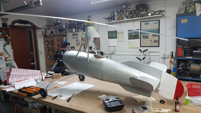
I decided to make the new C30 in wood with a proper 3 dimensional fuselage of the correct scale shape. As this would still be a test and development model I was happy to deviate from 100% scale on some aspects of the model in the interests of producing something that I could continue to learn from. I could always build a more accurate scale model later using everything I was hoping to learn on the way.
The first job was to draw a plan so I searched the internet for some 3 view drawings and then compared them to each other to find those that seemed the most accurate. I have found in the past that 3 view drawings are not always as accurate in dimensions as we modelers would hope. I also visited RAF Hendon museum in London as they have a Cierva C30. With permission from the museum staff I was able to get up close to the aircraft and take lots of pictures and all importantly some check dimensions. These dimensions were used to help check the 3 view drawings for accuracy.
I then loaded the 3 view into my CAD drawing package and proceeded to overlay the outline of the depron model over it. I was please to say the general outline shape of the depron model quite closely followed the full scale outline with the exception of the main rotor head position which had been moved back on the model, no doubt to aid getting it to balance. I decided to move the mast to a more forward scale position on my model as I intended using a much bigger motor and batteries. I then proceeded to trace over the outline of the 3 view on my computer to produce a basis for a set of working drawings. Quite a bit of time was spent developing a set of plans I could use to build the model but eventually I had something I could work with so I printed the plans out full size and started my normal series of checks to work out the likely finished weight of the model and where it would balance. This is done by making an estimate of the likely weight of each part and its position on the model. These checks showed that the model would likely be tail heavy so I took the decision to move the rotor mast back just a little to assist getting the model to balance without having to add lead.
With the plans redrawn it was time to start building. I opted to build a traditional box with spruce longerons and balsa uprights / diagonals. The spruce would be ¼” sq and would need to be bent through quite a big curve so I soaked the wood in the bath for quite a while to allow it to bend but it was still too stiff so I needed a plan “B”. At this point I decided to build something I had thought about for a long time but never got around to, - a wood steamer. I spend a day researching wood steamers and then build my own (maybe something for a future article??). The wood was put in the steamer and left for 30 minutes and then removed and it was nice any flexible and curved around the jig with no problems. Once it had dried, the uprights and diagonals were added and then the 2 sides, (built one on top of the other for accuracy), were jigged up on the bench and all the cross pieces and formers added. One area where I had decided to deviate from scale was to keep the central post for the mast as I felt this would make for a much stronger structure that just the scale pylon if / when?! The model tipped over during testing, a very wise decision as it turned out!
With the main structure assembled it was time to work out how to add the tailplane and fins. On the full size, the tailplane is quite unusual in that it has a normal upright aerofoil on the starboard side and an inverted aerofoil on the port side to assist in canceling out the roll from the rotors turning. I decided to copy this feature but as my rotors turn in the opposite direction I also had to reverse the tail aerofoil layout. To make a true scale model with the correct aerofoils on the tail the main rotor would have to turn in the opposite direction and this would mean having to run the motor in the opposite direction to normal for models. This is not so much of a problem with electric power, (although finding a good selection of opposite rotation props is not easy), my final goal was to build an even bigger model with a radial petrol motor so this is why I kept to my non scale design. It was quite an interesting job building half a tail upside down and I had to keep reminding myself of which way up to stick the ribs in. I decided to mount the tail on carbon tubes so they were easily removable as on the small model I had a couple of occasions where the model tipped over and the blades hit the upturned tips of the tail and damaged them. By having removable tailplanes, repairs would be easier. Once the tailplane centre section was mounted on the fuselage structure I could then add the semi circular formers to the outside and start adding the scale stringers. These were made from 3/16” sq balsa and of the correct number and location for scale.
The undercarriage on the C30 is quite a complicated shape but I took a decision to make it from piano wire and omit all the suspension the full size had. I made this decision as throughout the test flying with the smaller model it was always easy to land the model gently and omitting the heavy suspension components would keep the model lighter. A more scale undercarriage could be included on the next model.
The next consideration would be the construction of the head. I had already decided to build a bigger version of the small head as a first try rather than try to build a full scale head with flapping hinges, but clearly it would not be strong enough made from printed plastic, so it was time to fire up my trusty mill and lathe and get machining. Copying the geometry of the Coolwind’s head I machined parts from aluminum and set in ball races to carry the rotor shaft. The flex plate was made from 2 laminations of 1.5mm G10 fiberglass sheet with another disk of 1.5mm G10 underneath to support the weight of the blades at rest. Servos to control the head needed to be very powerful following the experience of the smaller model so a pair of 25kg torque servos were fitted with metal servo arms and connected to the head with 3mm steel rods encased with 4mm carbon tubes. This setup has proved to give sufficient rigidity to the quite long (500mm) pushrods and sufficient servo power to control the head.
There were no commercially available blades for a model of this size so they would have to be made from scratch. I sourced a plank of ½” thick Poplar from a specialist wood supplier and cut it into strips 30mm wide. To this I glued 60mm wide lengths of ½” balsa having taken this time to carefully select the balsa to get strips of as equal weight as I could. I was then preparing to shape them by hand when I had a stroke of luck and was introduced to a modeler with a spindle molding machine and a cutter of the correct shape to cut the aerofoil. A visit to him and I came home with 4 nice blades. Thank you John. I made 4 blades as there was always a chance that one could get broken during test flying. With the blade blanks made, ply reinforcements were glued to the root end and the blades carefully balanced both spanwise and chordwise before the 5mm attachment bolt holes were drilled. To add strength to the blades, especially the thin trailing edge, I covered the blades in Diatex 1000 covering and finished them with 4 coats of dope. During this process I checked the balance after each coat of dope and added more when necessary to keep them in balance.
Now it was time to cover the airframe and again, I used Diatex 1000. To work around the undercarriage the fuselage had to be covered in 4 pieces with the fabric carefully overlapped onto the stringers and then the overlap covered with pinking tape before the Diatex was shrunk with heat. 4 coats of clear dope were applied to seal the weave and then the whole model including the rotor blades was sprayed with silver dope. The flash on the fin was sprayed on with enamel paint. I resisted the temptation to start adding scale details at this stage as I was not sure how the model would fly and I half expected the model to get broken during testing and less detail would make for an easier repair. One detail that was necessary was a dummy engine to finish off the front of the model. I again turned to Tim to ask if he could scale up the original .stl file and print me a bigger motor. He originally said it would be too big for his printer but very shortly came back and said I had given him an excuse to buy a bigger printer so he would be able to do it.
Whilst waiting for Tim to print the motor I carried on with the fitting out of the model. I was struggling to decide what size motor to fit during the design phase so had designed the battery area to be able to take 2 x 5S 5000mha lipo’s and a stand off removable motor mount just in case I needed to fit a different motor. I decided to fit a 6065 motor of 420KV running on 5S swinging a 16 x 10 prop as I had this set up in another aerobatic model and it seemed to have plenty of power. An order was placed with 4-Max motors for the motor, prop and an 80 amp speed controller and this was duly fitted. A static test of the motor showed a very healthy thrust so I was happy I had made the right choice.
Soon the 3D printed motor arrived from Tim and I spent a happy afternoon gluing it together, painting it and adding a bit of weathering and detail (you can’t stop a scale modeler when he gets going !!!)
With the dummy engine installed it was time for the all important hang test and I was a bit disappointed to see that the model was tail heavy. The earlier decision to move the main mast back a little was correct but maybe I had not moved it enough. Oh well, I can’t do anything about the mast position now so out with the lead. I ended up adding 380g of lead to the motor mount to get the same hang angle as the small model. The total weight of the model came out at 6kg ready to fly, not to bad for such a big model with a 2.1m rotor diameter.
With the model finished and the radio checked it was time to take a deep breath and do a test flight. A few days wait for a day with a light but steady wind and it was time to go. After the normal model and radio checks I took the model to the far side of our runway after warning all the other pilots to keep an eye on the model as I really did not know how it would fly or if it would be controllable. I pushed the rotors by hand to get them moving and slowly started moving forward but the rotors were very slow to speed up so at the end of the runway I made a wide turn and came back downwind and then round again into wind all the time moving faster as the rotors speeded up. Just as I was getting to the end of the runway and thinking of turning again the model lifted off and slowly climbed away with no sign of roll or pitch issues. Setting the head over 4 deg to the left proved to be correct. I let the model climb into wind until it was a safe height and then started a turn, it lost a bit of height in the turn due to the extra drag of the control inputs but was safely round. I realised the motor was over ¾ throttle and in the turns I was flat out at times… but it was flying!!! Roll control was a bit soft but pitch felt fine. Rudder was also a bit soft but I could make wide turns in both directions. I made some more turns in both directions and then set up for a landing being very careful not to over flare as I know from my experiences with the small model that to much flare could cause the model to stop moving forward over the ground and then it could drift sideways in the wind and tip over on landing. Reducing the power produced a nice descent and a gentle back pressure to flare out and the model was down safe.
I was pleased the model had flown but clearly there were some issues to work through. The lightweight tailwheel assembly I had fitted was not really up to the job of all the taxiing about and would need to be improved, something that would have to be attended to in the workshop. I adjusted the rudder and roll for more movement, fitted a new set of batteries and decided to fly again. Spinning up of the blades was still a problem and I nearly turned the model over turning at speed back into wind for the second run up the runway but managed to correct it just in time and the model eventually took off. Control authority was better but the model did not really have enough power for anything more than very gentle turns. I knew from flying the small model just how much extra power you needed for tight turns and on this bigger model any attempt at a tight turn had the motor flat out and the model descending. Knowing this I gently flew the model around practicing approaches and circuits until the timer said it was time to land. Another gentle approach produced a nice soft touchdown. It was time to stop and have a think about the issues and how to solve them.
Back at home a bit of investigation revealed that putting shims under the back of the blade mounts to reduce the angle of attack of the blades would help them to spin up but at the expense of a little loss of lift. This was obviously worth a try so some shims were made from 1/16” ply sanded to a taper and fitted to the blade roots. I was a bit concerned about the possible loss of lift as to get that lift back I would have to fly faster and the motor did not have anything else to give but I thought it worth returning to the flying field just to taxi about and see if the blades would spin up better. The wind was a little stronger this time but the blades clearly did spin up a bit faster so I decided to go for it and the model lifted off right at the end of the runway and climbed away. It seemed to be climbing just as well as it did before I added the shims so I was happy to carry on with the flight. Power was still an issue but with gently flying everything was manageable. On landing however, with the stronger wind I flared a little too much and actually landed going backwards over the ground. Luckily it was not moving sideways and so did not topple over but another lesson learnt.
It now seemed clear to me that I needed to address the power issue and so decided to fit a bigger motor. I picked the biggest motor from the 4-Max range, a 6366 of 230KV. This would need a 10S lipo so I was very glad I had thought of this possibility during the design and made space to fit the batteries. With the new heavier motor, bigger prop, a 20 x 10 and the bigger speed controller I could remove all of the 380g of lead I had in the nose so I now had more power and the model weighed the same.
Back at the flying field I felt confident that power would not be an issue now but the blade spinning up issue still bugged me. The wind was quite light and even with the shims under the blades the rotor would not get up to speed on one run up the runway and I had to taxi back for a second run. Again it was difficult to turn the model at speed back into wind without it wanting to turn over but once in the air it flew much better with more than enough power to maneuver with ease, happily turning both left and right in tight turns with full rudder. The landing was again a non event in the light wind, having learnt my lesson about not over flaring. I went home happy that the power issue was resolved even though by running on 10S rather than the two 5S packs in parallel flight time was reduced. The rotor spin up issue was still a problem and lots of taxiing about to get the rotors up to speed was not a solution and I could see that the model could easily end up tipped over and broken. A new solution was needed and the obvious thing to do was fit a pre-rotator to the rotor head just like the full size to spin the blades up to speed before take off……but how?
I studied the full size which has a main gear under the rotor head driven by a pinion gear that is connected to a driveshaft connected to the engine by a clutch. It would be possible to copy this but to install it all would mean big changes to the layout of the fuselage components to the extent that it would probably be easier to build it all into a new fuselage. I was also concerned about the weight of all this but what if I mounted an electric motor on the head to drive the pinion gear. This is the way it is done on my Gyrone autogiro although at a much smaller scale.
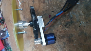
I needed a main gear, matching pinion gear, one way bearing and a suitable motor and speed controller. The obvious place to look for gears and bearings was the model helicopter world so a tri to my local Align Heli supplier identified that a Trex 700 gear set was the right size. Parts were purchased and then it was back to the workshop to machine up a new gimbal assembly, bearings and motor mount. Of course the bearing and pinion gear had holes that were too big for my use so I had to machine up sleeves to reduce the diameters to suit my needs but in a couple of days I had the gears mounted on the new gimbal. I had no idea what power motor I needed but a club member mentioned he had a crashed Dynam Hurricane model that used to swing a biggish 3 blade prop so why did I not give that a try. As I had nothing else in stock I thought why not so collected it and drilled the gimbal beam to suit the motor bolt spacing. I fitted a speed controller in the head fairing and made a wiring loom, with capacitors in the loom because of the long cable length, to take power from one of the 5S packs. I figured the head motor would not have to run for very long and so the batteries would not go far out of balance.
The whole set up was mounted in a big vice on a heavy table and power was applied to the motor and to my relief the motor started to turn the head and accelerate it well. I put a tachometer on the blades and it showed around 400rpm, perfect, that should be fast enough to enable a short take off. I did another spin up to check everything was ok and just as I reached full power the motor died and all the magic smoke came out. The motor had burnt out. Luckily the speed controller was OK but I now needed a new motor and clearly 5S was too much. To my dismay I could not find another Dynam motor listed as a spare and there was nothing written on it to tell the spec. To make matters worse, the mounting bolt holes on the Dynam motor were 17mm pitch and all other motors of that size I looked at from various suppliers were 25mm pitch which was too wide for my gimbal assembly. This would mean making another complete gimbal assembly to fit the replacement motor. I put the word out to all my modeling friends asking if anyone knew of the whereabouts of another Dynam motor and thankfully I got a favorable reply from a friend of a friend’s friend who had broken his model and the motor was available. The deal was done and the new motor installed but now I needed to find a new power solution as 5S was obviously too much. I needed 4S, I considered regulators but they were too big and heavy so instead settled for a small 1550mha 4S pack that I could fit near the mast to avoid upsetting the balance.
With the new head installed it was back to the field for another go. This time I taxied to the end of the runway engaged the head motor and spun the blades up to full speed and then cut the motor and started the take off. The model lifted off after only a short run and was flying as well as ever even with the additional weight of the head parts and battery. Happy days.
This project is still very much in the development stage. I have a practical flying large C30 but there is so much more to learn and develop in order to build a large fully scale and detailed model. I will spend the summer testing and developing ideas for this big model to see if it is really practical to build a model twice the size of the current one. One area currently under development is a set of built up rotor blades as it will be impossible to have solid blades on a bigger model. I have a set of built up blades finished and have made one flight with them so far and they have completely changed how the model flys. It is much more responsive to head control inputs and generally does not fly as nicely. I need to investigate why this is so I can bring those thoughts to the design of a bigger model. There are some major practical issues to overcome such as an undercarriage which will be over 1.6m wide and a model that stands 2m high and is in one piece!!!
Watch this space.
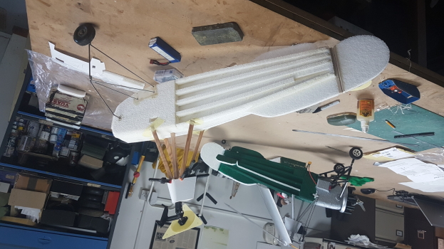
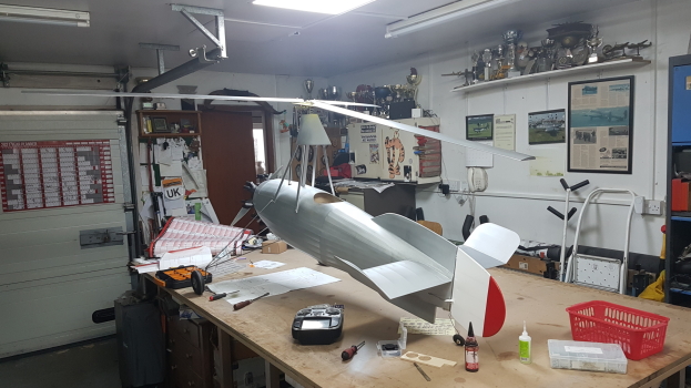
Original foam model build progressing well. Tim’s original model in the background for reference
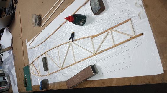
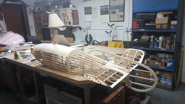
Basic fuselage frame under construction
Trial fit of tail parts
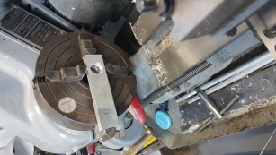
Machining the gimble plate for the head bearings
Completed head assembly
Final set up and checking the radio gear
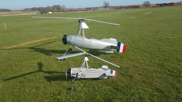
Small and large models together gives an impression of size
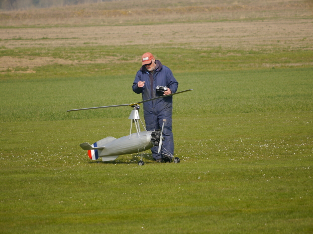
Final checks before the first flight
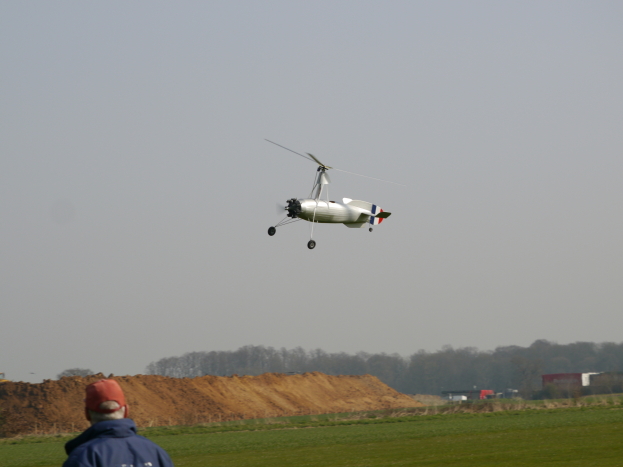
It flys !!!

| Visitor Counter: | |||||||
 |  |  |  |  |  | ||