
27 MHz Reed Transmitter conversion to 2.4 GHz
Project
John decided that he would like a vintage style transmitter to fly his vintage aircraft with. A friend of ours Stuart Mackay has had many 27 MHz transmitters converted to 2.4GHZ, so he gave us contact details.
First, there is a website dedicated to vintage RC equipment. http://www.singlechannel.co.uk/.
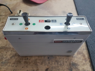
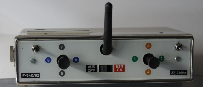
This site has conversion details the software (Arduino Sketch) electrical drawings and equipment list, Phil the owner is very helpful. John obtained a Grundig Variophon transmitter.
As this is a reed transmitter this is how the modern version will still work.
John required
that the outside of
the transmitter should look as authentic as possible
The transmitter was dismantled leaving only the switches in place, these were then carefully cleaned with contact cleaner. This transmitter would be powered by two 18650 batteries. The batteries we used were approximately 3700 milliamp hours. There are some that state a much higher rating but these appear to be fake. The electronics consist of a transmitter module and a small Arduino board plus a few other components.
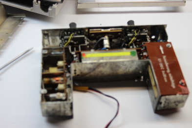
The outer casing removed ready for the big strip down
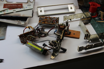
The strip down has begun, the only parts to be kept are the switches, their mounting plate, and the chassis ( metal frame on right-hand side of photo).
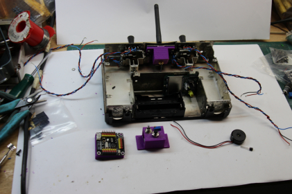
Start of the reassembly.
Encoder is on the left.
Purple fixing were printed on the wooden 3D printer out of ABS.
Encoder board mounted
4 in1 RF module mounted on
the right-hand side. The purple mount in the left of centre of the picture carries transit speed pot and Aux functions. (these are not needed in flight)
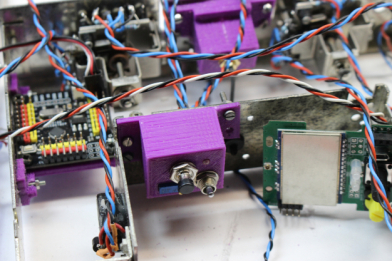
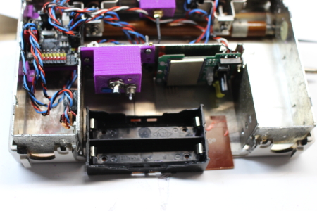
Battery box will be attached to
battery hatch cover so that the whole carrier can be removed
in order to remove batteries for charging.
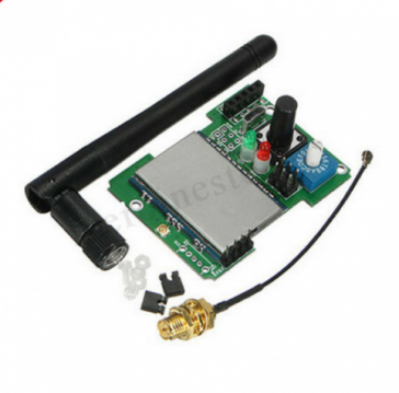
This is the Jumper 4in1 modules, it can be set to PPM mode or serial, ours is to PPM
with a protocol that Futaba RX understands SHSS in our case
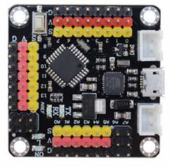
This is the Arduino board that we used, it is a DIYMore mini strong board. The advantage of this board is that the sketch ( Program) can be loaded and modified via the micro usb port.
Once the transmitter was assembled I found that it would not bind with the RX. The reason for this was that the RF module is a multi function unit and is easy to adjust if the transmitter that you are using has an LCD screen to adjust binding tolerances. Being a vintage transmitter ours does not, Stewart Mackay put me in contact with a friend, Michael Kitchen, whose hobby is resurrecting 27 MHz TX's as 2.4 GHz one's, he has written a sketch that uses the protocol selector switch to select segments of the binding range by turning the selector when required. With this sketch uploaded the TX and RX bound with no problems. John is at present testing this TX and hopefully COVID-19 permitting we will have photos of some flying with this setup.
TX is now finished, during testing, a problem was discovered. This did not show up whilst testing using an internal combustion eng. The throttle output moved between 1 and 2 ms (actually 2 to 1ms) This caused problems when an electric motor was tried the ESC would not arm. it was found The throttle output was always starting at 2ms even when throttle output was reversed, the output still started at 2ms. Mike Kitchen came over to help investigate the problem he found that the problem was caused by the way the Futaba SHSS protocol was being processed by the 4in1 jumper 2.4ghz
module. He got around the problem by changing a couple of lines in the Arduino sketch. This fix, unfortunately, disables the throttle reverse function in the TX. This is not an issue for us.
Many thanks to Mike for his time and expertise. The TX will be used shortly and photos will be added of it operating a vintage electric-powered model.


| Visitor Counter: | |||||||
 |  |  |  |  |  | ||