
Westland Whirlwind
Please note that this project is on hold until Andrews estate is settled
Andrew has taken on quite a challenge with his latest project. The Whirlwind does not have much wing area and with a high mounted tail and big nacelles, it will be a challenge to keep weight and balance under control.
Construction is Andrews's typical mix of traditional construction and blue foam with fiberglass cowlings. Details of the model are:-
Span 10 ft.
Scale approx 1/4.5
Length 7.4 ft.
Weight, maximum hoped for, 40 lbs.
Wing area 12.3 sq. ft. Loading 3 lbs per square ft.
Control by basic 8 channel Futaba FHSS (at this time) and using various Hitec servos with likely two Rx`s, one at the front and one at the rear.
During the build, Andrew has been considering making the model electric powered rather than petrol so as not to spoil the cowling with cylinder heads exposed but of course essential for cooling. However, the construction to date will allow him to choose later. The incidence of the tailplane is also a bit of cause for concern as experience has shown that `high` tails usually need positive incidence (or should that be negative? Leading edge high) so allowance for adjustment is being built in just in case it should be necessary. The Fowler type flaps will be in either two or four parts rather than one piece centre span which is complicated as they hinge from the bottom of the nacelles.
Recommended reading `Whirlwind` by Victor Bingham, Airlife Publications for full-size details.
More info and photo's to follow as project progresses
Working on the tail assembly
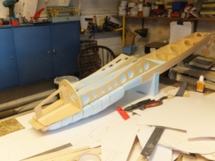
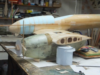
Fuselage under construction showing balsa and ply framing with blue foam infill. note rear of the fuselage is conventionally planked.
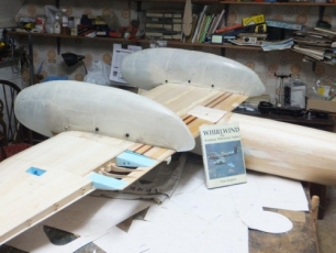
Wing centre section with a combination of balsa, ply and blue foam ribs.
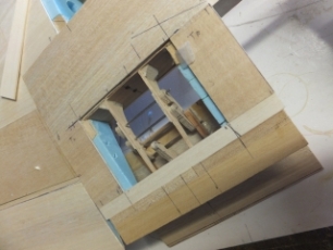
Work progressing on the fuselage and starting to frame up the cockpit area
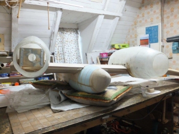
Trial fit of the nacelles. Andrew made his own plug and mold for the nacelles and laid them up in glass cloth and epoxy resin.
Another view of the large nacelles.
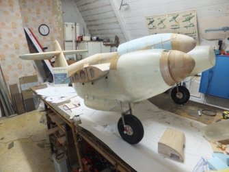
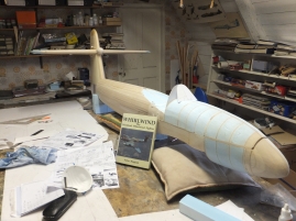
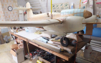
Model sitting on its undercarriage for the first time. The pictures also show the epoxy glass nacelles being `trued-up` for thrust line adjustments. Also, the blue foam sandwiches used at the front fuselage. Foam is also utilised for the outer wing panels, tailplane and fin and all these parts are covered with balsa and skinned with epoxy glass. However, the foam sandwich of the fuselage is not covered with balsa but two layers of light cloth and epoxy. The rear fuselage is standard balsa planking with a traditional build for the wing centre section which is also balsa sheeting and all glassed.
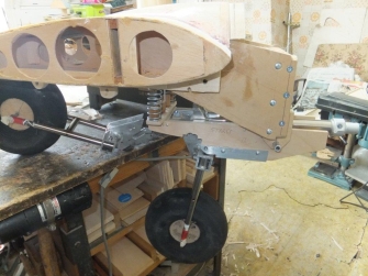
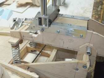
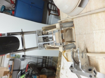
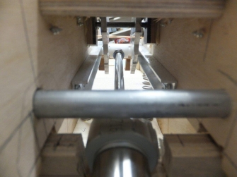
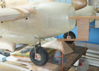
The Whirlwind u/c design is a bit different and untried. The weight had to be kept well forward, air operated but with positive `up` locks. The cylinder is a commercial unit with 100mm stroke positioned between ply sides to form a box. The inner faces of the box have alloy channel `rails` in which the nylon rod attached to the piston rod slides to engage between the upper leg forks which is a common method of operation. Andrew confesses to being not much of a metalworker and wished to avoid oleos especially the twin-legged variety so attached this undercarriage box to pivot at the front and hang from below the engine mounting. The rear of this box is supported and held in position against compression springs which attach to the main spar base. The leg is positioned midway between these two mounting points and carry a home made 6.5 inch dense foam tyre and nylon hub.
This whole assembly is still a "work in progress" with some fettling still to do.
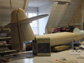
Model fully rigged to check alignment
Jig fitted onto firewall to check the amount of noseweight that will be needed


| Visitor Counter: | |||||||
 |  |  |  |  | | ||